Double-DIN Radio Conversion & Servo-Driven Climate Control
Overview
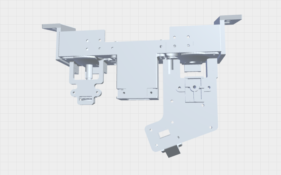
My 2003 Mitsubishi Lancer ES shipped with a single-DIN radio opening. I wanted to drop in a double-DIN head unit instead — but a double-DIN unit is roughly twice the vertical height of a single-DIN one, and the factory climate-control assembly sat directly beneath the radio bay, in exactly the space the taller unit needed. There was no double-DIN kit for this dash, so the only way to make the swap was to pull the factory A/C control assembly out of its slot entirely and design a new structure that relocates it elsewhere in the dash cavity — while still routing its vents, its cable/servo linkages, and the two knobs a driver actually touches.
That rebuild is this project: a from-scratch, custom-fit enclosure system, modeled part-by-part in SolidWorks and printed at home on a Creality Ender 3 V2. Along the way, I also used the rebuild as an opportunity to fix a separate, well-known failure on this car — the temperature-control knob's mechanism seizing and snapping its drive rod — by converting that side of the assembly from a cable to a servo and potentiometer.
Quick Facts
- Rebuilt assembly is 3 SolidWorks sub-assemblies (13 parts) feeding one top-level assembly: parts common to the whole structure, the airflow-direction control side, and the temperature-control side.
- The temperature knob was converted from its stock cable mechanism to servo + potentiometer control — fixing a common Lancer ES failure where the knob mechanism seizes and forcing it shears the plastic drive rod.
- The airflow-direction knob kept its cable mechanism (no equivalent failure mode) but was still rebuilt from scratch with its own click-detent generator and gear hub.
- Every part is designed to print without support-heavy overhangs, on a near-flat base, split small enough that one failed print costs an hour, not a full rebuild.
- Lesson learned the hard way: the first set was printed in PLA and deformed in a hot parked car over the summer. ABS or another high-temperature filament is the right call for anyone building this for real use.
Design Approach
The whole assembly is deliberately broken into many small, single-purpose parts rather than one or two large printed shells:
- Small parts, not monoliths. A large single-piece print has more surface area for warping, layer separation, and multi-hour failures. Splitting the housing into individual pieces means one failed print costs an hour, not a day — and a damaged part in the field can be reprinted and swapped without pulling the whole dash apart again.
- Flat base, minimal overhangs. Each part is oriented and split so it sits on a near-flat base on the bed wherever geometry allows, with overhangs kept shallow — less support material, cleaner bottom surfaces, and far fewer mid-print adhesion failures on an open-frame printer.
- Reinforcement at load points. Anywhere a part sees repeated mechanical load — knob rotation, bracket screws, mounting tabs — the model adds fillets and local wall thickening. Threaded fasteners carry the joints instead of relying on the print's own layer adhesion, with screw and nut lengths chosen to fully span the depth of their holes rather than bottoming out partway through. Countersunk and counterbore holes were deliberately avoided too — both cut directly into the wall right where the plastic needs to stay thickest.
- Fillets where space allowed. Fillets and rounded transitions were added wherever the surrounding dash geometry left clearance for them, softening stress risers and making the printed parts look closer to an OEM-molded piece than a visibly 3D-printed bracket.
Two Knobs, Two Fixes
On the temperature-control side of the assembly, the model leaves an allowance for a potentiometer instead of the original cable-actuated mechanism. That's not a simplification — it's a fix for a well-known failure on the 2003 Lancer: the factory temperature knob mechanism is prone to seizing, and forcing a stuck knob shears the plastic rod that drives it. Once that rod snaps, the cable mechanism is effectively dead.
Rebuilding this side of the assembly as servo-driven, with a potentiometer standing in for the knob's position sensing, sidesteps the failure mode entirely — no cable, no rod to shear. It also folds naturally into the rest of the electronics already going into this dash for the head-unit swap.
The airflow-direction knob next to it — the one that picks which vents the air comes out of — didn't have that failure mode, so it kept a cable-actuated mechanism. It was still rebuilt from scratch, with its own click-detent generator, gear hub, and a printed cable holder and cover to carry the relocated cable run.
Printed Hardware
These are the actual print files from the build, grouped into the three sub-assemblies: parts common to the whole structure, the airflow-direction control side, and the temperature-control side. Drag to rotate, scroll to zoom, or grab the raw STL for any group below the viewer.
Parts List
| Group | Part | Role |
|---|---|---|
| Common | Front circuit housing | Encloses and locates circuitry/wiring for the front-facing control cluster |
| Main knob housing | Shared housing structure that both control knobs mount through | |
| Storage-to-A/C bracket — left | Structural bracket tying the storage bay to the relocated A/C box | |
| Storage-to-A/C bracket — right | Mirrored bracket for the right side of the same joint | |
| Flow-direction control side | Base plate | Structural base the rest of this sub-assembly builds on |
| Hemispherical housing | Outer housing shell that seats against the dash on this side | |
| Click-detent generator | Produces the tactile click feel as the vent-direction knob is turned | |
| Gear hub | Gear interface translating knob rotation into the mechanism's motion | |
| Cable holder | Retains and routes the relocated actuator cable for this control | |
| Cable holder cover | Closes over the cable holder to keep the run captured | |
| Temperature control side | Hemispherical housing | Outer housing shell on the temperature-control side |
| Knob rod | Interface rod linking the dash-facing knob to the internal mechanism | |
| Potentiometer holder | Mounts the potentiometer that replaces the stock cable mechanism | |
| Potentiometer | The servo-control sensing component itself, seated in the holder above in place of the stock cable takeoff |
Print Process & a Lesson Learned
Every part was printed on a stock Creality Ender 3 V2 — an open-frame FDM printer with no enclosure, so ambient temperature and drafts matter to print quality. Parts join with screws at the reinforced points described above rather than glue or press-fits alone, so anything can be disassembled and replaced on its own.
PLA melts. This lives behind your dashboard, in a parked car, in summer.
The first full set was printed in PLA. It held up fine — until a stretch of scorching US summer heat, when the interior of a parked car climbed well past PLA's softening point and one part warped and deformed in place. Nothing catastrophic, but enough to need a reprint. The parts are designed for FDM printers generically, but given where they live, ABS or another high-temperature filament is the right call for anyone building this for real use — not PLA, however tempting it is to print with.